We may receive a commission when you use our affiliate links. However, this does not impact our recommendations.
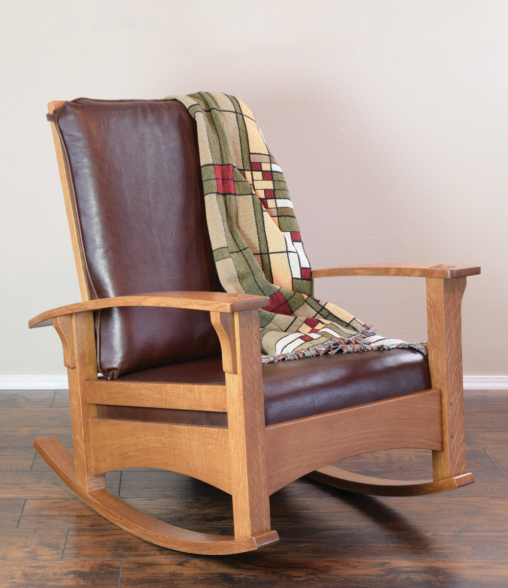
This modified design builds off a classic Morris chair.
Inspiration for the next project can come from many sources, but for me, all it took was a trip to an antique furniture dealer. Legacy Modern is a boutique dealer in Portland, OR specializing in arts and crafts furniture, and they happened to have an original Morris chair that caught my eye. It was a Gustav Stickley #336 Morris chair, and I thought it would be the perfect starting point for a Morris rocker.
So, I took detailed measurements from the original chair and created a CAD drawing. However, I wanted a rocking chair rather than an armchair, so I had some additional work to do. To my knowledge, Gus Stickley never produced a bow arm Morris rocker. So, I surrounded myself with rocking chairs to ferret out the keys to good rocker geometry.
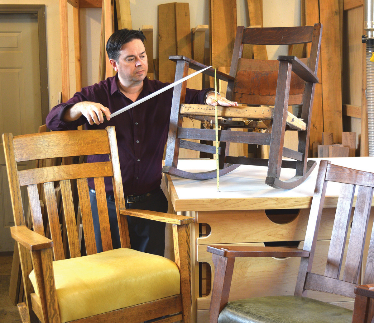
1. Surround yourself with rockers. Sit in more than a couple rocking chairs and measure up each version you encounter. See which dimensions and attributes will create a comfortable rocker for you.
I acquired several rocking chairs—from antique to reproductions—to test and measure. I discovered that despite the varied size and style of these chairs the rockers were nearly universal. I chose the rocker radius I liked best an amalgamation of two of my favorite rockers, which turned out to be r=44“.
The first thing you notice about the antique Gus Stickley Morris chair is the organic shape of the bowed arms. Next perhaps you’ll see the side seat rails are set at a dramatic angle. This pitches the seat backwards, making it the most comfortable chair I’ve ever perched in. Usually the seat rail angle and slip seat angles are independent from one another. With this design, both are set at the same angle, which results in a finished cushion that is parallel with the side seat rails. Although angled joinery adds some complexity, I think it’s a design element worth preserving.
Two Bending Forms
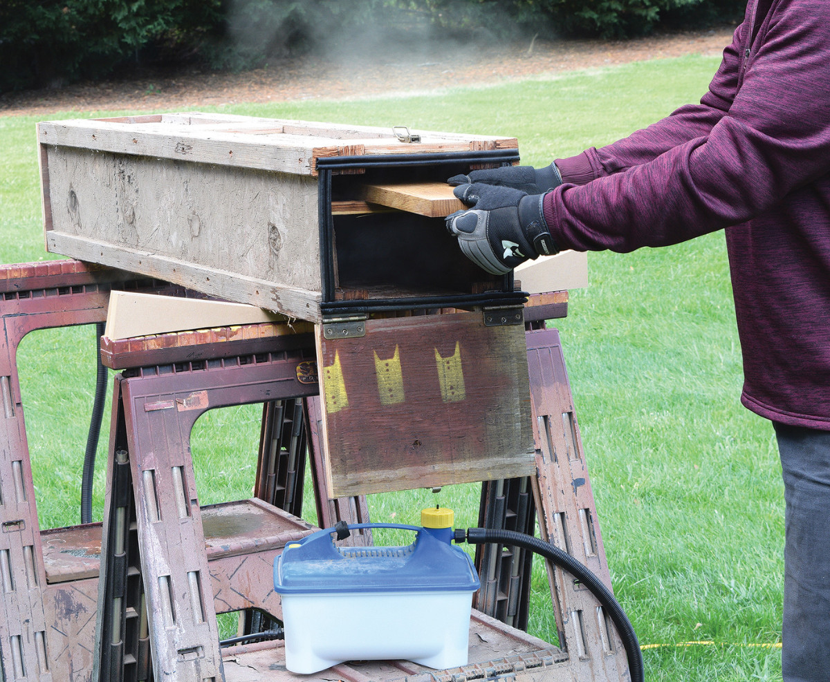
2-3. Start with the armrest projecting one inch beyond the form and clamp it in place. Note the arched form is elevated on blocks to allow access for the clamps.
You’ll need two different bending forms: one for the bow arms, and another for the rockers. The radius of the bow arm form is 74“ (the form bulges 2 3/4“ over a 40“ span), and the radius for the rocker form is 42“ (the form bulges 5 1/6“ over a 40“ span). The arms can be steam bent, but the tighter radius of the rockers require them to be glued laminations. A common structural failure on steam-bent antique rockers is of splitting the wood.
 To make the best use of time, start with the steam-bent armrests. The armrests need to steam for 60 minutes and stay clamped in the form for 24 hours. To set the bend, remove the armrest from the form and expose it to dry heat for 24 hours. During this step, it’s helpful to apply a ratchet strap around the armrest that holds the curved shape, while still allowing air to circulate. I used my lumber kiln to apply the dry heat, but a pair of heat lamps works just as well. Whatever you do to the first armrest do the exact same to the next one. The goal is to create two identical curves.
March On with the Legs
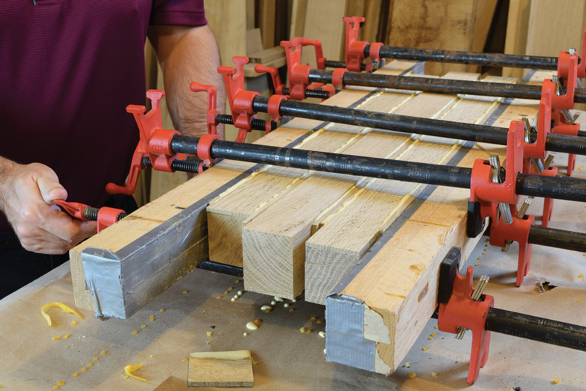
4. Gang a few legs together and glue 1/4″ thick veneer strips on each side. Thick clamping cauls help ensure a good bond.
We’ll build this as a standard Morris chair first, then trim the legs to make it a rocker. (This gives you one last chance to bail out at the end or stay on course for a rocking chair.) Additionally, the extra leg length is helpful when it comes time to permanently set the rocker angle.
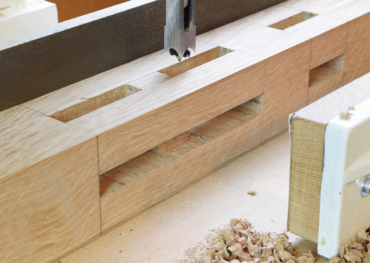
5. The seat rail mortises are 51/2″ long, so I divided them into two smaller mortises. First, cut mortises to a depth of 13/4″.
My preferred method for laminated legs with through tenons is to start with 10/4 stock and add thin veneers on two faces. This gives the best of both worlds—quartersawn figure on all four sides—as well as no visible glue line in the exposed tenon.
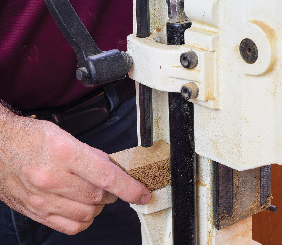
6. Then add a 1″ spacer block to the mortiser’s depth-stop, to limit the depth of cut to 3/8″. Then clean out the area between the two mortises. This lets you preserve the depth stop setting as you proceed to the next leg.
Mill rough leg blanks to 21/2“ wide x 23/8“ long, and glue 1/4“ thick veneers on two faces. This will result in a leg blank that’s a little oversized, but you’ll have better luck with the glue joint if you stick with 1/4“ thick veneer strips. Now plane the blanks to a finished size of 21/4“ square which will leave each veneer about 3/32“ thick.
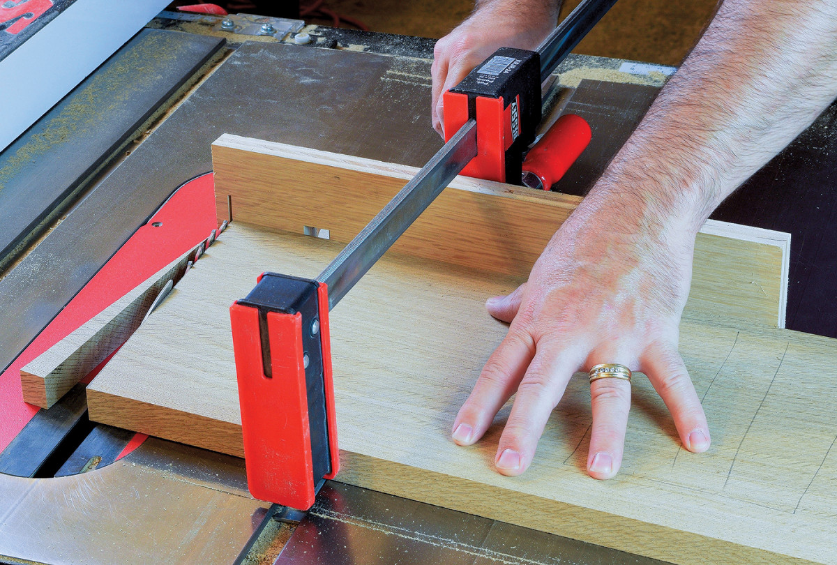
7. Start with a ‘rail blank’ and angle both ends to 5.5°. Secure the blank to a miter gauge with a clamp and make the angled cuts at the table saw.
Cut the legs to rough length, and lay out the mortises. Despite the seat rails being angled, all the leg mortises are straight and square. We’ll deal with the angles when it comes time to tenon the side rails. Chop the leg mortises, 14 in all, with your preferred method. Since the mortises for the seat rails are 51/2“ long, dividing them into two smaller mortises will help preserve leg strength. I left 1“ of solid wood between the divided mortises, which are each 21/4“ long.
Right to the Rails
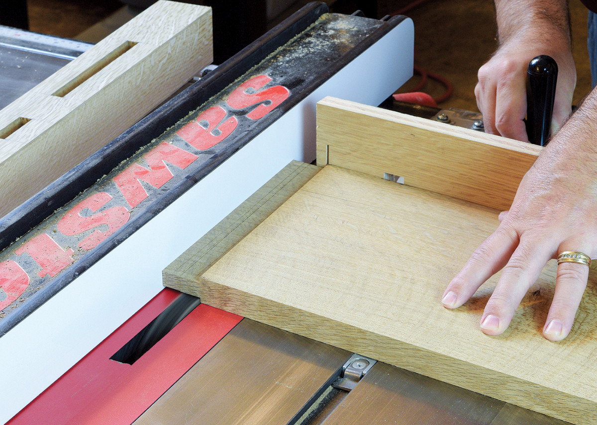
8. Then switch to a full dado stack, and with your miter gauge still angled to 5.5°, form wide tenons on both ends of the blank. Once the tenon cheeks are complete, you’ll rip the narrow rail free.
The front and rear rails have standard, square tenons. Also, this chair design doesn’t splay outward from back to front as many chairs do. Instead, the side rails angle downward, and require angled tenons. The easiest way to cut this type of tenon is to angle the ends of the rail first, then cut the tenons with a dado blade. If you have a board wide enough to yield a narrow side rail, plus a wide side rail, here’s a little trick. Start with a rail blank sized 7/8“ thick x 81/2“ wide x 2711/16“ long. Angle both ends at 5.5° to make a rhomboid shape (this removes about 13/16“ length from opposite corners). You’ll cut the tenons with two rails still connected as one board. Install a full dado stack, and use the rip fence as a reference to set the tenon length.
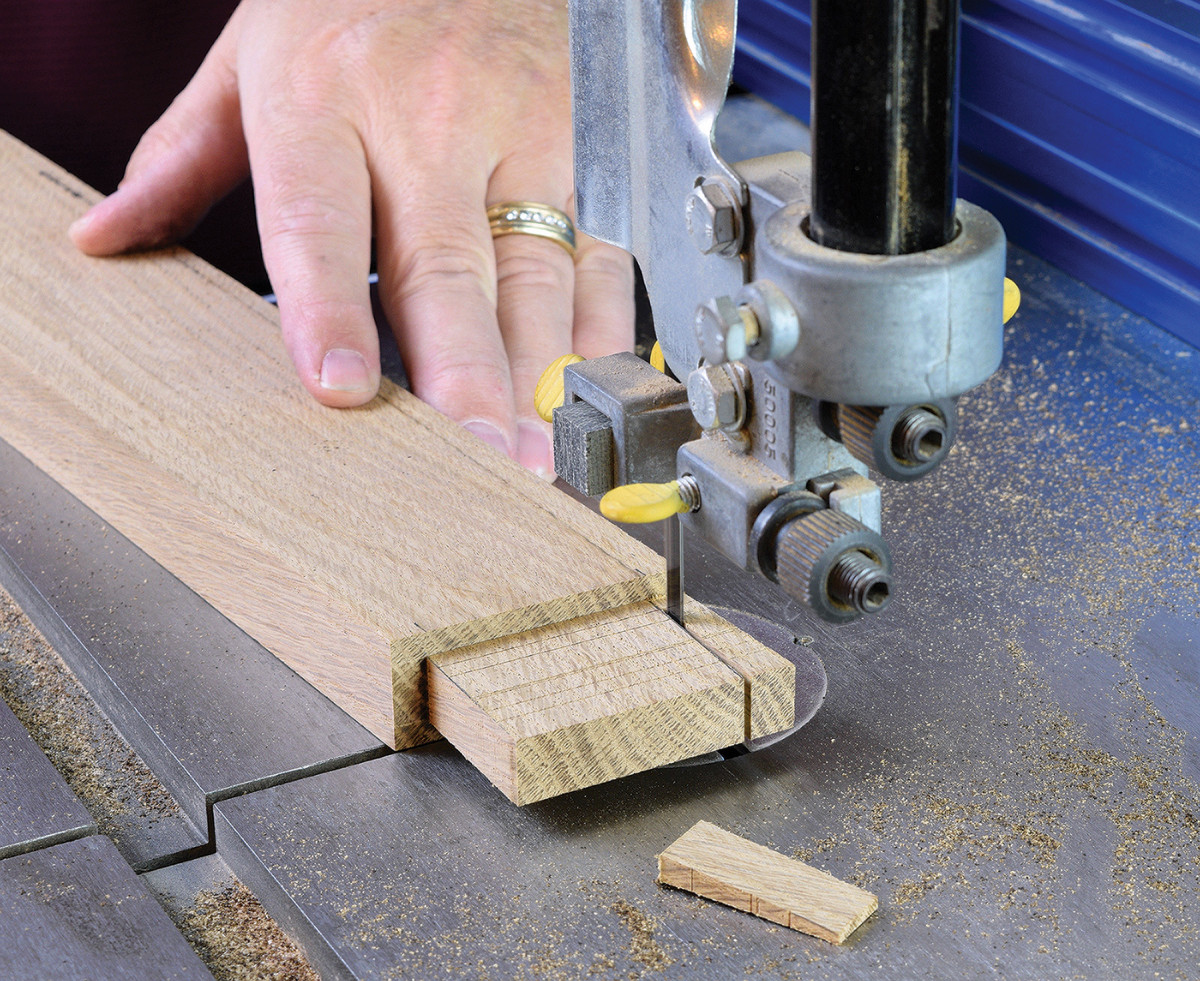
9. The bandsaw is a quick and accurate means of trimming the tenon shoulders. Complete all four angled side rails in this manner.
Then rip the narrow rail free and complete the tenon shoulders at the bandsaw. This method ensures your side rails will have consistent angles and has the added benefit of a great looking grain match.
There are a couple more steps to get the tenons fitting properly into the legs. Divide the wide tenons to match the leg mortises. This is a pretty easy task if you turn the rail up on end and pass it over a dado blade. Finally, miter the ends of the intersecting rails so they won’t interfere with one another.
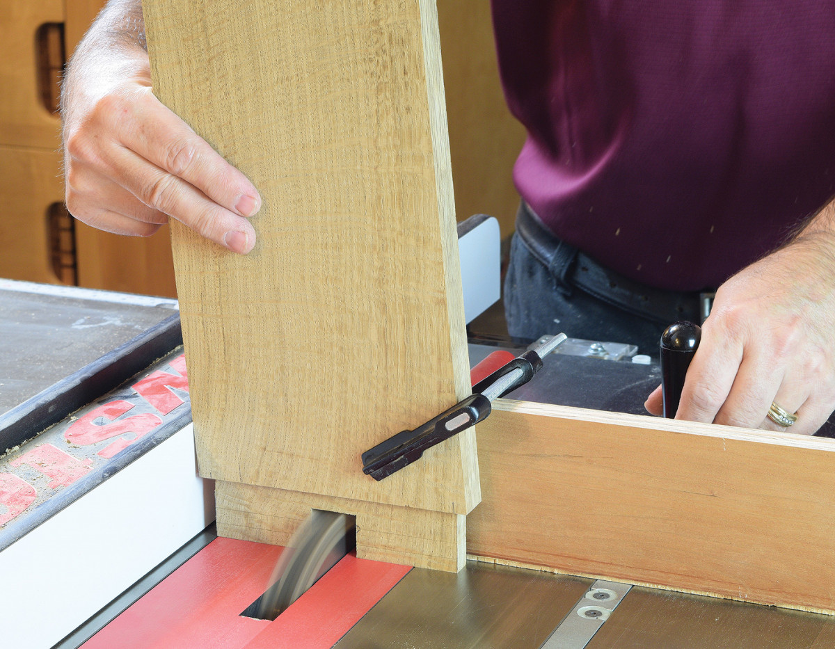
10. Mark the location of the 1″ square notch in all wide tenons. With a dado blade and miter gauge setup on the table saw, turn the rail up on end to make the notch in two passes.
Next drill a pair of 1 1/2“ deep holes, one in each rear leg, to receive the backrest pivot pins. The center of these 5/8“ diameter holes need to be located 15 3/8“ from the bottom of the leg and centered on the thickness of the leg.
Armrests
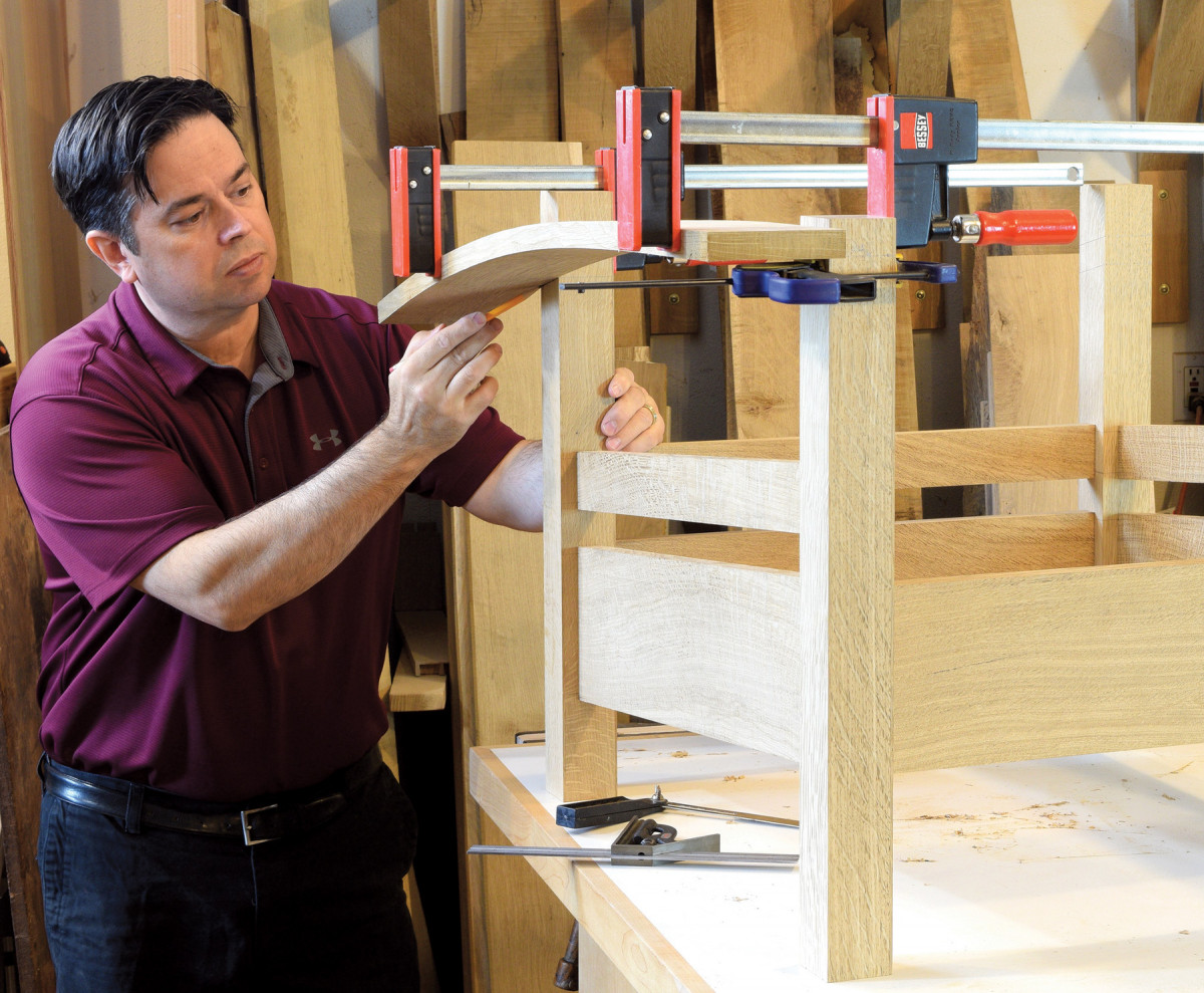
11. The shoulder on the front leg is fixed at 225/8″ from the floor. Position the bow arm on your line, and mark where it intersects the rear leg. While you’re at it, mark a line above the arm and a cut-line that’s 1/4″ taller.
Now mark the tenon locations atop the front legs. Then dry-assemble the chair and set an armrest on your mark. While holding the armrest in position alongside the front leg, mark where the underside of the armrest intersects the rear leg. The schematic diagram shows that the long tip of the shoulder on the rear leg should be approximately 20 1/4“ from the floor. Ultimately, the rear legs need to conform to the shape of your armrests, so some variation is expected here.
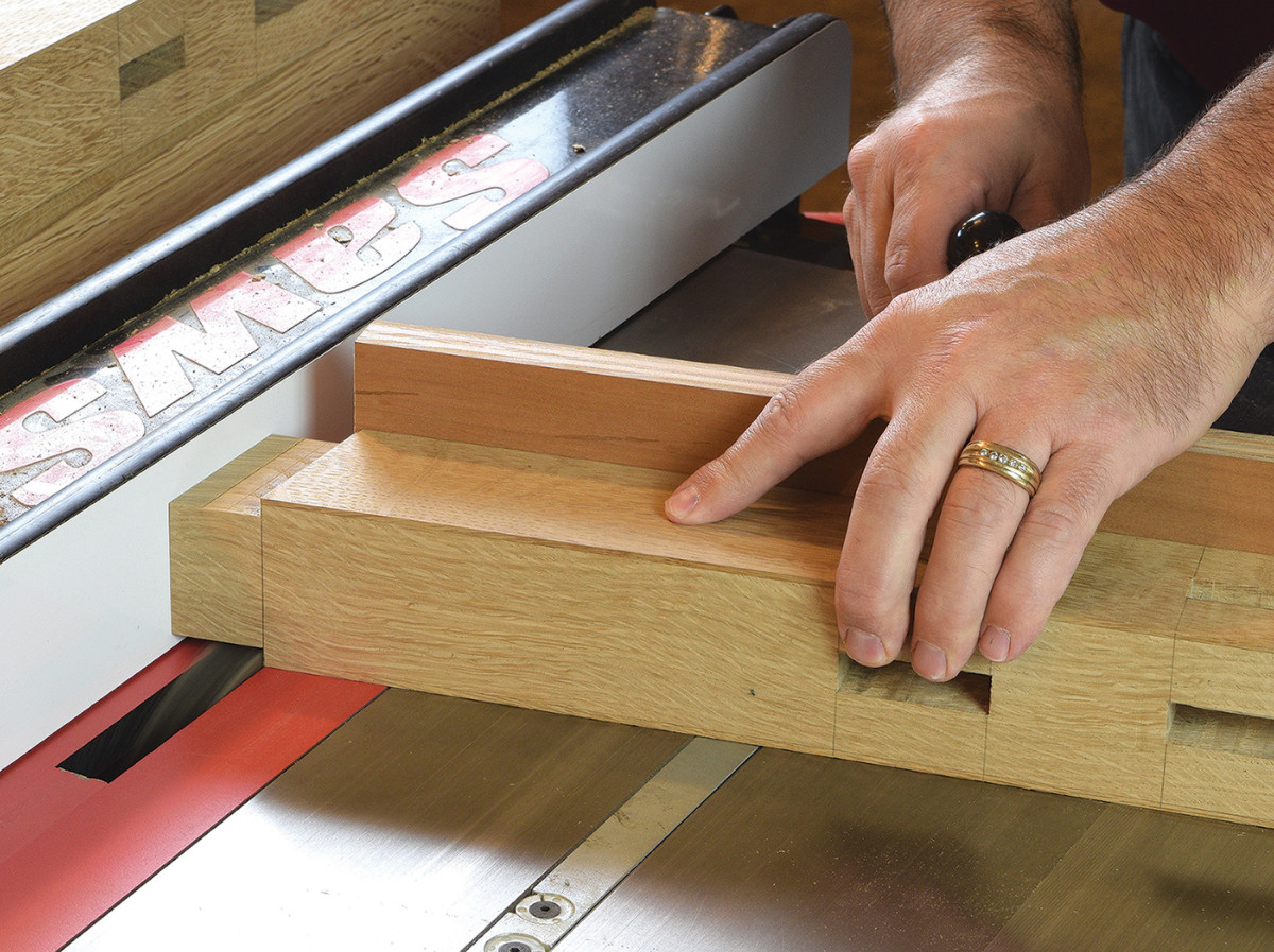
12. An exception to the rule. Instead of cutting the mortise first with the armrests, you’ll cut the tenon first. Use an angled miter gauge and dado blade to handle two sides of the tenon.
With the height of the rear legs established, go ahead and complete the tenons atop the legs. I used a fine-toothed dado blade and miter gauge to cut these tenons at the table saw. The tenons are 1 3/4“ square and should project 1/4“ above the armrests. Once the tenons are formed, set the armrest on the shoulders, and transfer the mortise location directly from the tenons. With the armrest situated so close to its final position, there’s no confusion where to locate the mortises. Cut the armrest mortises with a mortiser or by hand. The front mortises are square to the face of the armrest, while the rear mortises are angled.
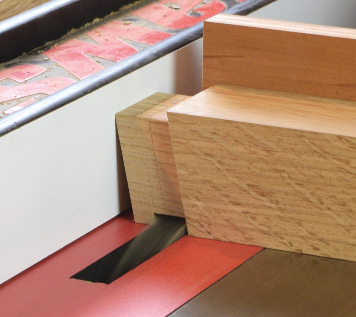
13. Return the miter gauge to 90° and cut as close to the shoulders as possible.
When cutting the rear mortise, it helps to support the armrest with a curved wood block. This will keep the armrest from flexing, and also helps to minimize chipout. If you can’t control chipout sufficiently with a support block alone, you may need to transfer the mortise location to the underside and score the perimeter with a chisel. Final fitting of the mortises is done with files and sanding sticks. It’s helpful to turn the armrest 180° from its intended position to isolate each mortise and tenon joint. Once the front mortise slides over the front leg tenon, move on to the rear mortise. Make small adjustments and test your progress frequently. Back-bevel the mortise walls slightly to sneak up on a snug fit.
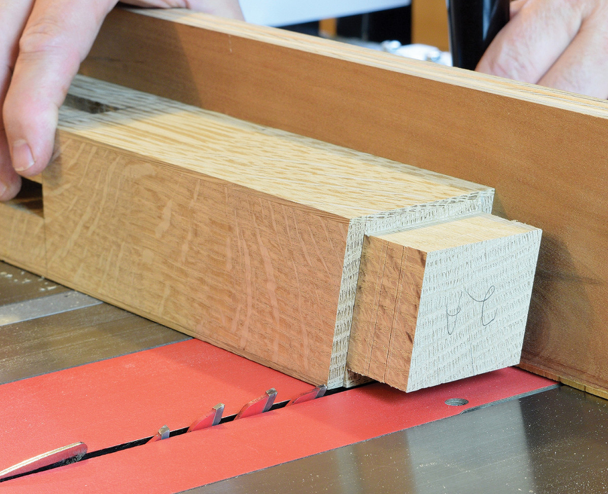
14. Then switch to a combination blade and angle the arbor to 12°. Trim the sliver of waste that remains with this step-up.
When building Morris chairs, I feel like it’s all downhill once the armrests are fitted. While many steps still remain, much of it is just busywork. Trim the armrests to a finished length of 36“. You’ll make the cut from the back of the armrest at a 12° angle. Now you’re ready to drill a series of four 5/8“ diameter holes in the armrests for adjustment pins. Then complete the tapered cut at the outer back edge of the armrests.
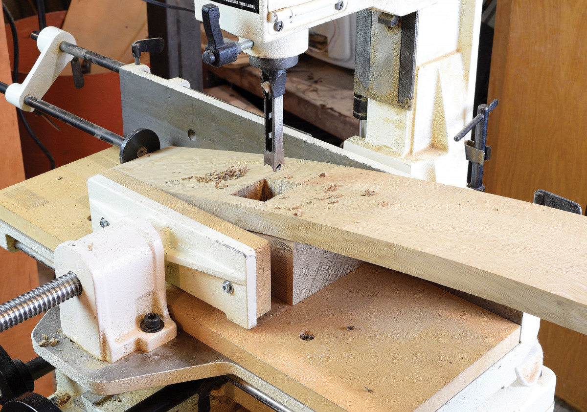
15. Position the armrest so the front face is level and support it with a curved wooden block. Stay inside your layout line and refine the mortise with hand tools.
Rout a groove in each leg to receive the corbels. These grooves are 3/4“ wide and 5“ long, and just 3/16“ deep. Make the four corbel blanks and form a shallow stub tenon on each. Once the corbels fit nicely in the groove go ahead and cut them to final shape. Ease the edges of the parts you’ve made and give everything a thorough sanding.
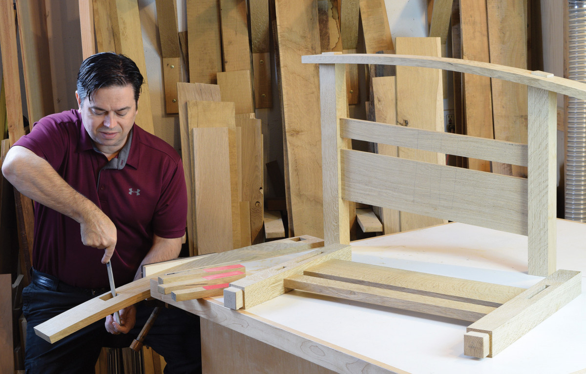
16. Fine tune the mortises with files and sanding sticks. Once the front mortise is sized independently, start working on the rear mortise. Undercut the mortise wall slightly to make installation easier.
One of the final details is to chamfer the tops of the legs in a decorative pyramid shape. While there are several ways to accomplish this, ranging from a chop saw to block plane, I haven’t found an easier way than sanding them to shape. I routinely use an oscillating belt sander to gradually form the pyramid shape. A tilting table on the sander combined with a miter gauge helps guide the operation. Start with 50 or 60 grit sandpaper and work up through 120 grit.
Rockers are Bent Laminations
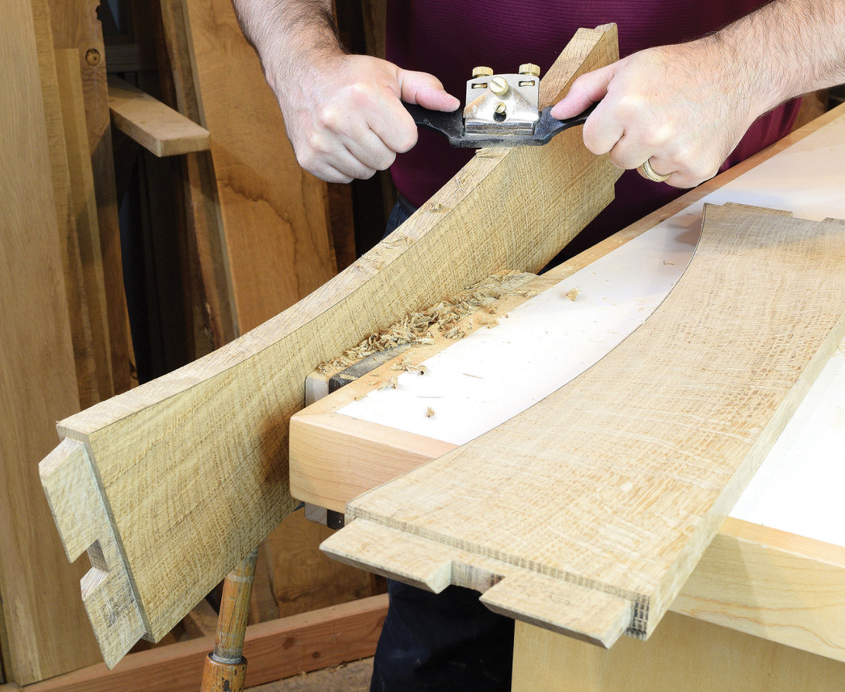
17. Rough cut the arched seat rails at the bandsaw, before fairing the curve with a spokeshave and sandpaper.
So, this is your final chance to leave it is a Morris chair, or forge on to complete the Morris rocker. Or perhaps one of each? Use your second bending form to laminate the rockers. Cut 3/16“ x 2 5/8“ strips on the bandsaw, and plane them down to 1/8“ thickness. The strips are about 40“ long, and you’ll need eight layers for each rocker. Try to cut them consecutively from a thick plank for the best grain match. If that’s not feasible, arrange the layers for the most consistent look.
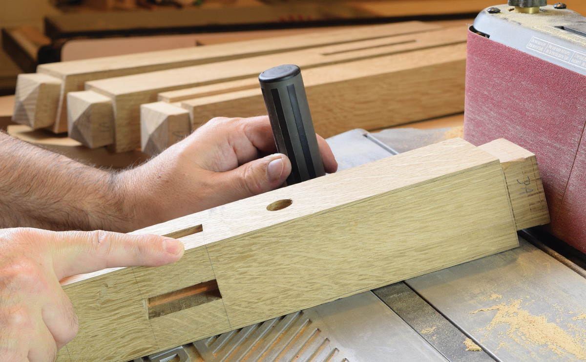
18. An oscillating belt sander with tilting table makes quick work of forming the pyramid shape atop each leg. Work through the grits to smooth the facets.
When I was building the MDF rocker form, I used four 3/4” layers and added some scrap pickets to act as a fence. Screw the pickets to the form and cover any exposed areas with packing tape to keep the glue from sticking.
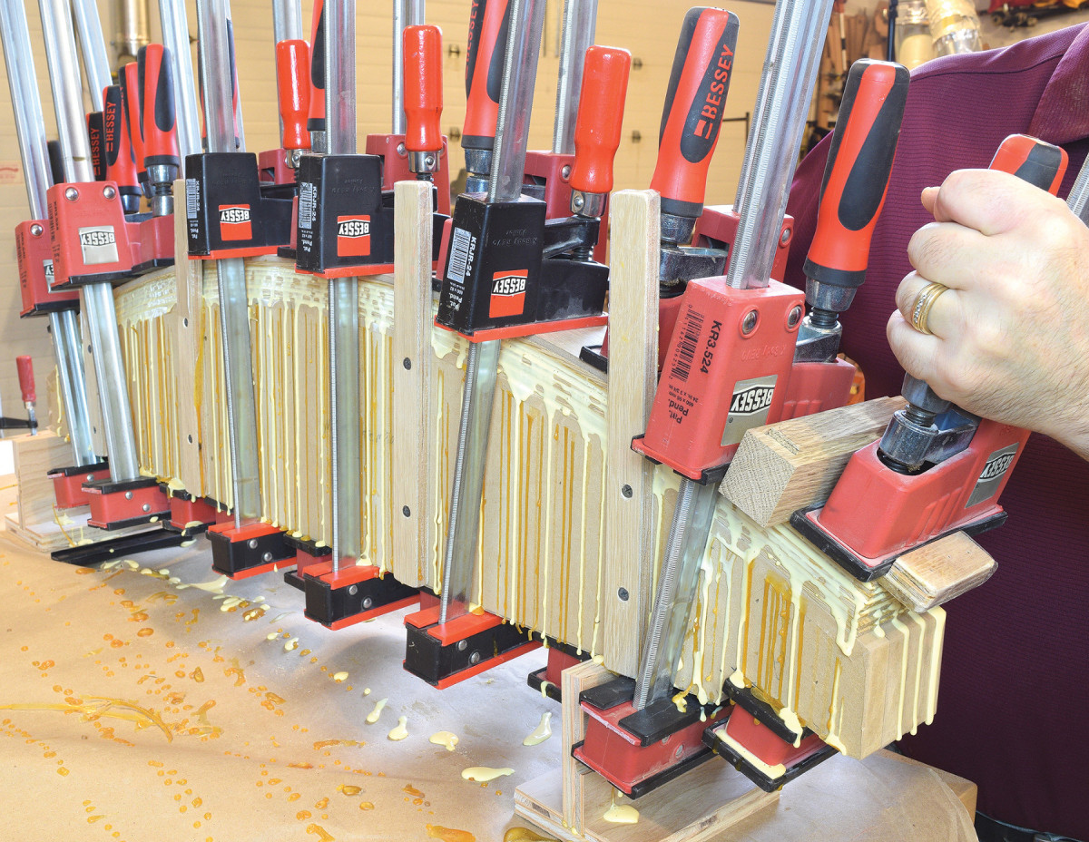
19. The rockers are laminated from eight 1/8″ thick strips. A piece of 1/4″ plywood is used as a caul to distribute the clamping force evenly.
The diameter of the rocker form accounts for minimal springback that is typical with standard yellow PVA wood glue. If you choose to use a specialty glue or epoxy, it may alter the finished radius of your rockers. Use a 3“ wide smooth paint roller to apply glue to one face of each strip of oak. Lay a strip of 1/4“ plywood (also covered in packing tape) on top of the laminated strips as a clamping caul. Start clamping at the center of the form and work outwards as you go. Leave the rockers clamped in the form overnight, and once cured, dress them at the jointer and rip them to finished width. Position the rockers next to the legs and mark the final leg length. Disassemble the chair and trim the legs to your line.
Side Assemblies
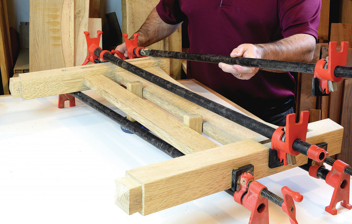
20. Once the legs are angled to final length, glue the side assemblies together. Use spacer blocks between the rails to prevent the angled joints from racking.
Glue up the side assemblies with two legs and two rails each. The armrests can be attached in a separate step, once the other clamps are removed. Next clamp the rockers in position and drill for dowels with a 3/4“ brad point bit. Then use an age-old technique to attach the rockers: wedged dowels. I have a Limbert rocker from 1908 that used the very same technique (more than a century later, it’s still rocking). Slit the dowels on the distal end, to receive a small wedge. Drive the dowels through holes in the rockers and add the wedge to permanently affix them to the legs. Trim the dowels and give things a final hand sanding.
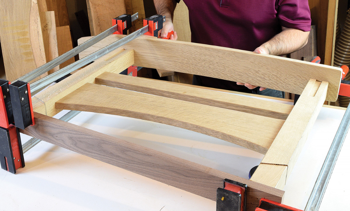
21. Next make an angled clamping aid from your leg cutoffs and a scrap board. Secure the leg cutoffs to the board so they align with the legs. This greatly simplifies the task of clamping the armrest in position, for a stress-free assembly.
When these side assemblies have cured, connect them with the front and back rails. Drill the armrest joints for 1/4“ dowels to hold everything in place. Likewise, the lower mortise and tenon joints are drilled for 3/8“ dowels. Glue the corbels in place, adjusting the angle of the rear corbel to fit the armrest.
Ladder Back
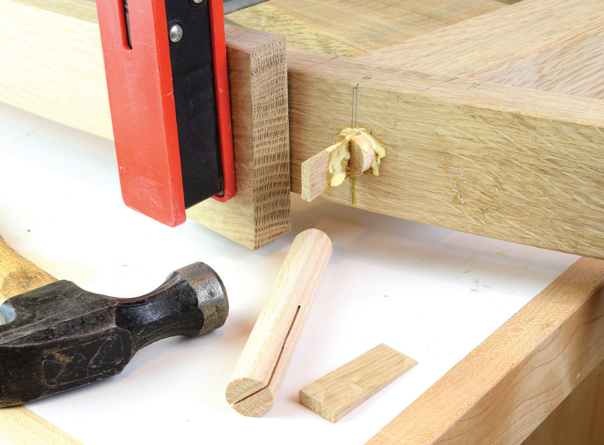
22. Clamp the rocker firmly in place to drill 3/4″ holes. Temporarily remove the rocker to apply glue to the end grain and reinstall the clamp set-up. Drive the dowel in place first and add the wedge last.
The backrest consists of only 6 parts; two uprights and four rails. Start by making the two uprights, which are 1 1/4“ thick x 1 3/4“ wide x 27 1/2“ long. Lay out and cut the mortises in the uprights, making note that the top rail is wider than the rest. You’ll need one 3 1/2“ long mortise and three 21/2“ long mortises in each upright. These mortises are all 3/8“ wide, and 1“ deep.
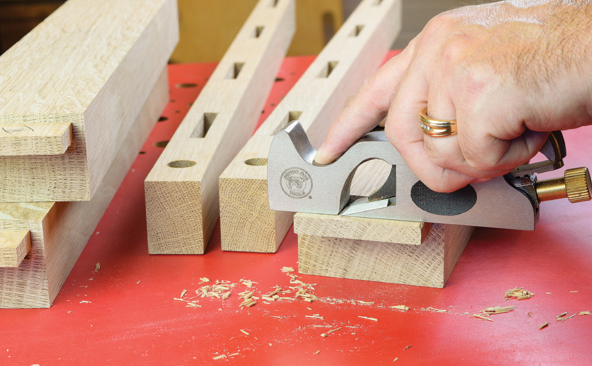
23. Use a shoulder plane to shave offset tenons to final size.
The easiest way to make the curved backrest rails is to start with 8/4 stock. Lay out the offset tenons and curve the rails planning for a finished thickness of 3/4“. Complete the tenons on each rail with a dado blade and miter gauge setup at the table saw. Once all the tenons are complete, start shaping the curves at the bandsaw. Finish the rails by sanding the curves smooth, front and back. Keep moving things along by drilling holes for the pivot pins and gluing the backrest sub-assembly together.
Final Details
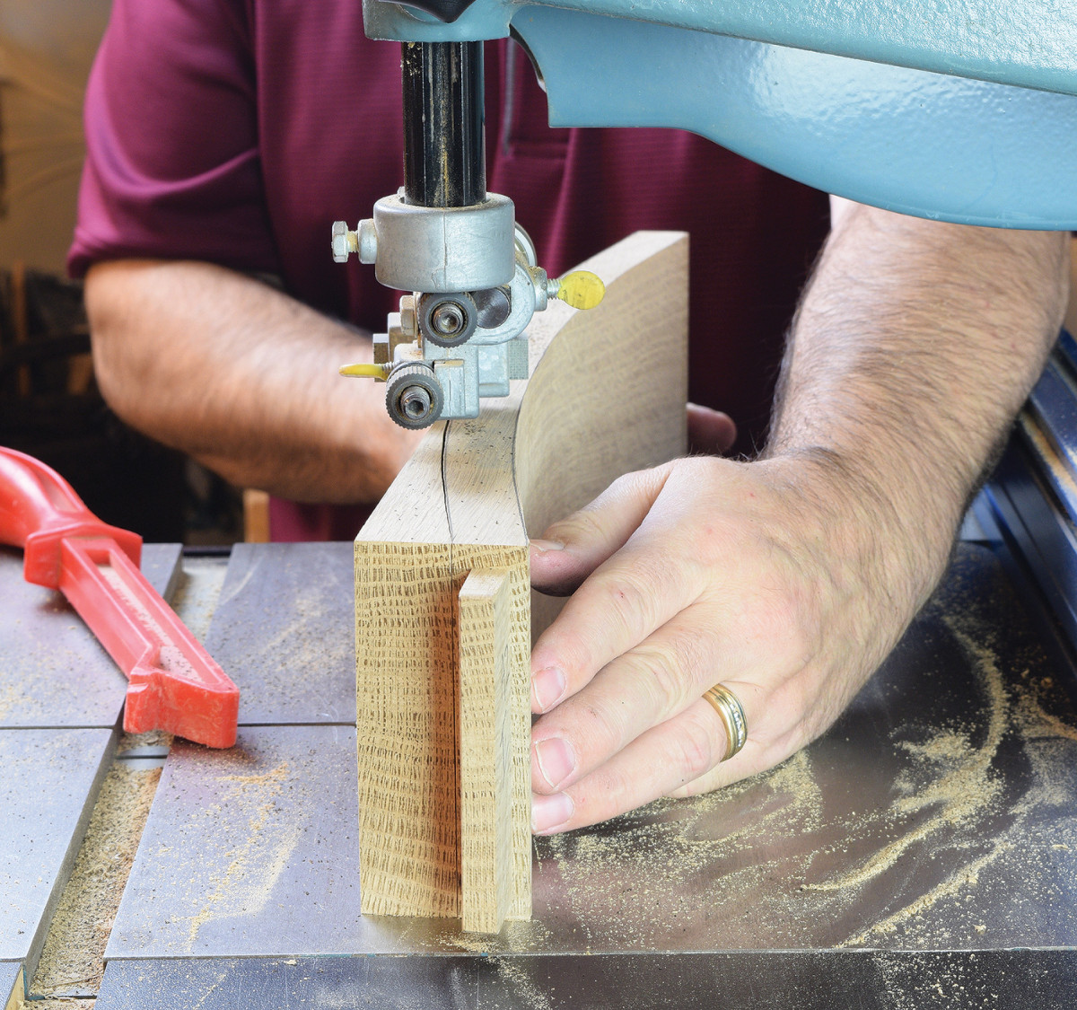
24. Once the joinery is complete, cut the curved backrest rails at the bandsaw.
Whether you’re planning to tackle the cushions yourself or not, you’ll need to make a frame for the slip seat. Size the frame 1/4“ smaller than the opening in all directions to allow room for the cushion material. The seat frame uses half-lap joinery, which is a strong and traditional joint for this application. Glue the four parts together, and round over any sharp edges to protect the upholstery.
 Four corner blocks are required as well. Pre-drill and counterbore the corner blocks, before permanently installing them on the chair. Mount the corner blocks as low as possible, so the seat height can be adjusted with ledger boards as needed.
 Now make the pivot pins and adjustment pins. Either turn them on a lathe or make them from oak dowels. In the latter case drill a 1“ diameter dowel to receive a 5/8“ diameter dowel and glue them together. The final parts required are a pair of hexagonal wooden washers which help to center the backrest between the armrests. The wooden washers are 2“ diameter with a 5/8“ diameter hole.
Apply the finish of your choice and turn your attention to the upholstery. The seat cushion is layered from three different densities of form and is about 7“ thick overall. The backrest cushion is a single piece of soft 3“ foam, wrapped in polyester batting.
Here are some supplies and tools we find essential in our everyday work around the shop. We may receive a commission from sales referred by our links; however, we have carefully selected these products for their usefulness and quality.


