We may receive a commission when you use our affiliate links. However, this does not impact our recommendations.
Stickley Arm Chair
by Seth Keller
Click Here to see the matching Stickley dining chair.
| This arm chair goes with the Stickley dining chairs featured on page 44 of the August/September issue of American Woodworker. As you can see from the drawings and cutting list given here, this chair is simply a larger version of the dining chairs, with arms. That means all the basic building steps are the same—you can follow the how-to instructions given in the magazine to build the arm chair. The instructions that follow show how to make and install the arms.
For convenience, the part letters in the arm chair cutting list and drawings are simply doubled: Part A for the dining chair is Part AA for the arm chair, and so forth. Of course, the part dimensions and rail angles for the arm chair are different, because it’s bigger. Here’s how to make and attach the arms.1. Make a pattern for the arms (Part VV, Fig. AA, and Fig. KK) and trace them onto the arm blank. Bandsaw the shape of the arms out of the blank. Sand smooth (Photo 1). 2. Cut out the arm brackets (WW and Fig. LL). Rabbet each bracket to overlap the seat rail. 3. Using the mortising jig, rout a 1/4″ x 1″ x 3/4″ deep mortise in top end of each bracket. 4. Bandsaw the taper on the outside face of each bracket. Remove the saw marks by sanding or scraping. 5. Drill 3/16″ dia. shank holes for the fastening screws. Counterbore these holes for the wooden buttons (XX). Finish sand both brackets and ease the edges with the 3/32″ roundover bit. 6. Clamp each bracket to the seat rail and set the arm on top, so the notch meets the back leg at the correct height. Scribe the bracket’s location on the bottom of each arm. Hand-chop mortises in the bottom of each arm to match the mortise on the bracket. 7. Assemble the arm and bracket and fit the assembly to the back leg. Scribe the angle where the arm meets the back leg (Photo 2). 8. Install loose tenons and glue and clamp the arms and brackets. 9. Position the arm-and-bracket assembly on the chair. Drill 7/64″ pilot holes for screwing the brackets to the seat rails. Then fasten the brackets with glue and #10 x 1-1/2″ flat head screws. 10. Fasten the arm to the back leg. First, drill a countersunk shank hole for the screw through the leg. Then drill a pilot hole into the arm. Carefully drive a #10 x 2″ flat head screw into the back of the arm (Photo 3).
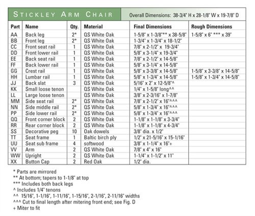
Cutting List
|
Click on any of the images to view a larger version
1. Saw out the arms, one right and one left, after using a pattern to trace them onto a blank.
2. Scribe the angle where the notch in the arm meets the back leg. A spring clamp and the arm bracket hold the arm at the right height. Saw the notch angle or pare it with a chisel.
3. Drive a screw to hold the arm to the back leg. The arm and bracket are already glued and fastened. Drill a pilot hole before driving the screw, to prevent cracking the end grain.
Fig. BB Exploded View(Note: There’s no “Fig. AA.” In the original story, Fig. A shows the mortising jig that’s used to build the chairs.) Fig. CC Back Leg
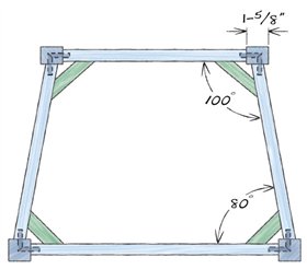
Fig. DD Side ViewFig. EE Front View: Back AssemblyFig. FF Front view: Front AssemblyFig. GG Crest and Lumbar Rail DetailsFig. HH Top ViewFig. JJ Seat FrameFig. KK Arm PatternFig. LL Arm Bracket
|
Here are some supplies and tools we find essential in our everyday work around the shop. We may receive a commission from sales referred by our links; however, we have carefully selected these products for their usefulness and quality.


