We may receive a commission when you use our affiliate links. However, this does not impact our recommendations.
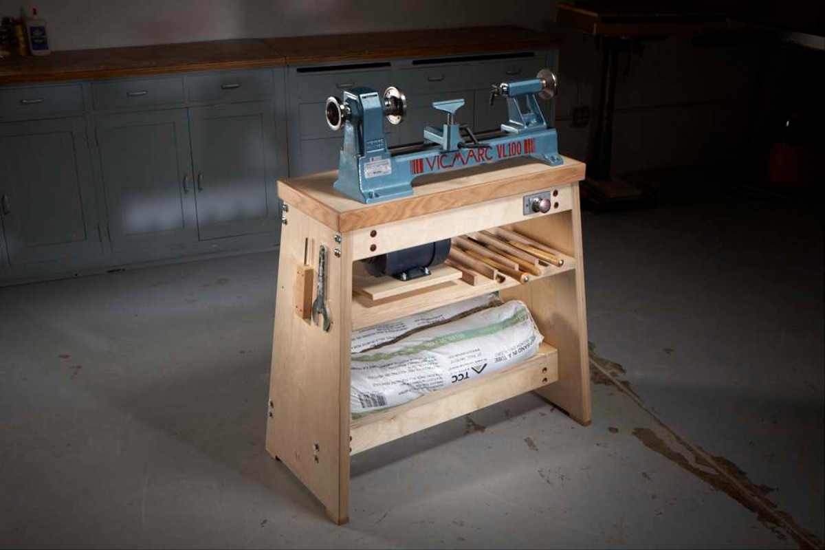
Build a professional-quality stand that’s stable, strong and heavy.
A good stand is just as important as a good lathe.
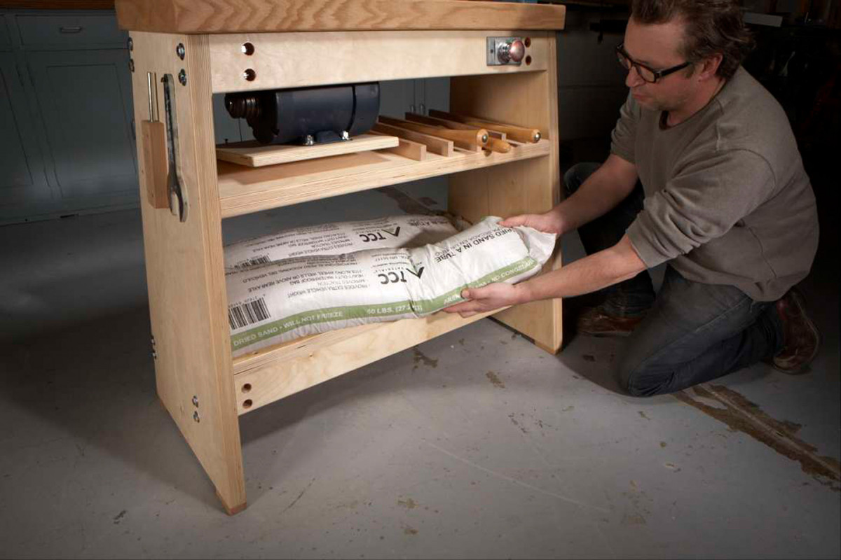
Serious beef. Double and triple thicknesses of 3/4″ plywood, plus 120 lbs. of sand, provide ample mass to absorb vibration.
As a professional turner, I can’t emphasize enough how important it is to have a stand that’s stable, strong and heavy—particularly for bowl turning.
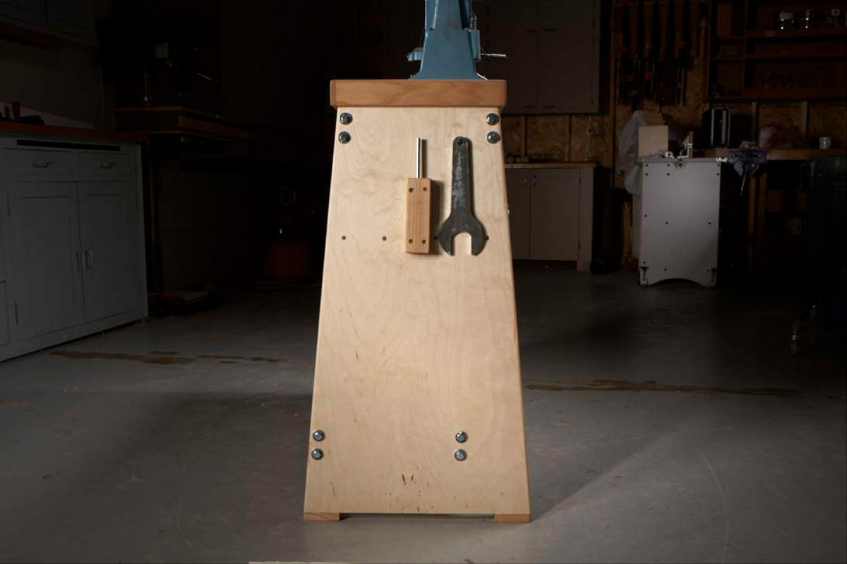
Stable stance .
This one meets all those requirements, and is better than many steel stands, yet it’s just made from plywood. Building your own stand has another major advantage: You can customize its height.
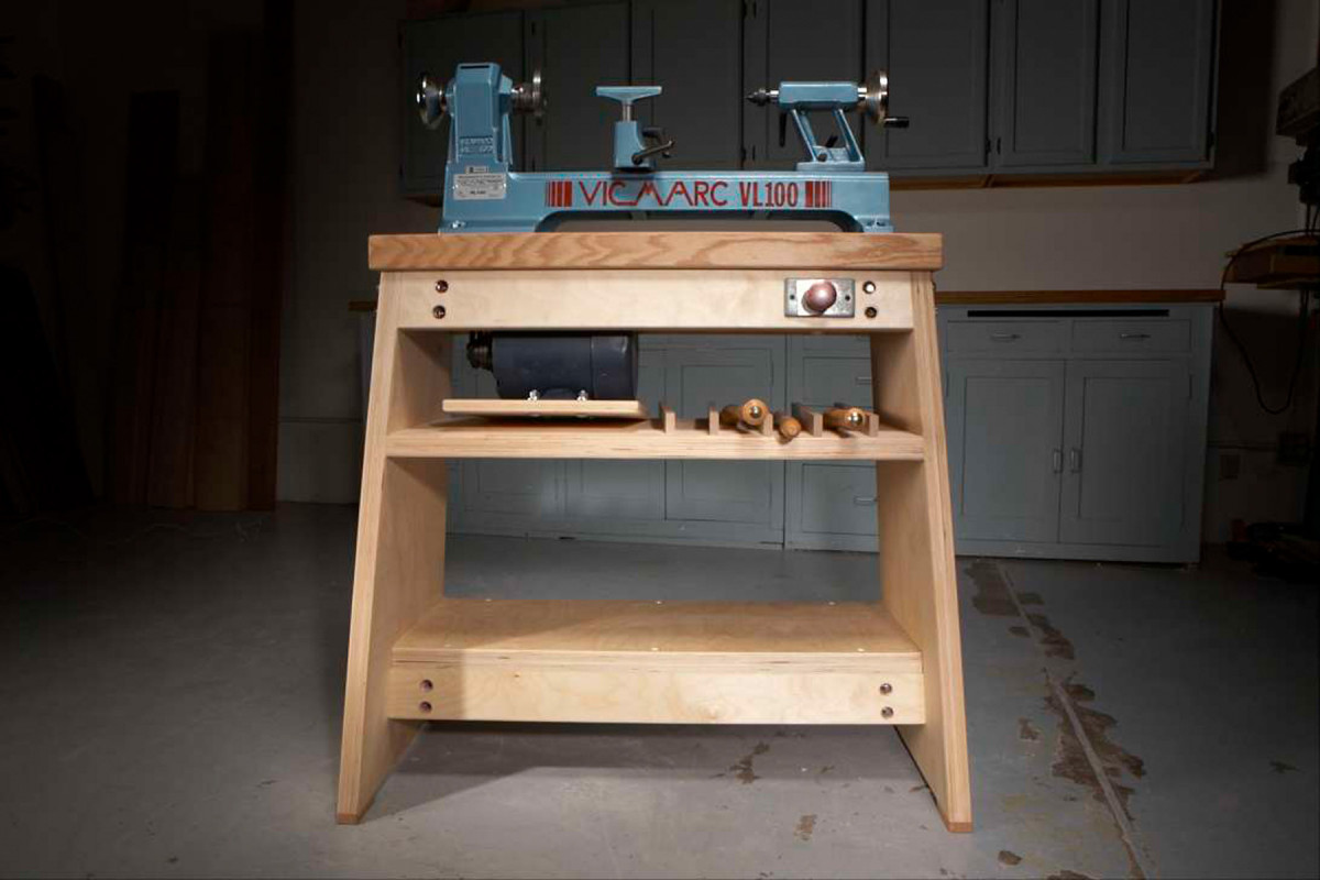
The legs splay out in both directions.
Turning on a stand that’s the right height allows you to control your tools much easier, and is less fatiguing, too. Time to do it!
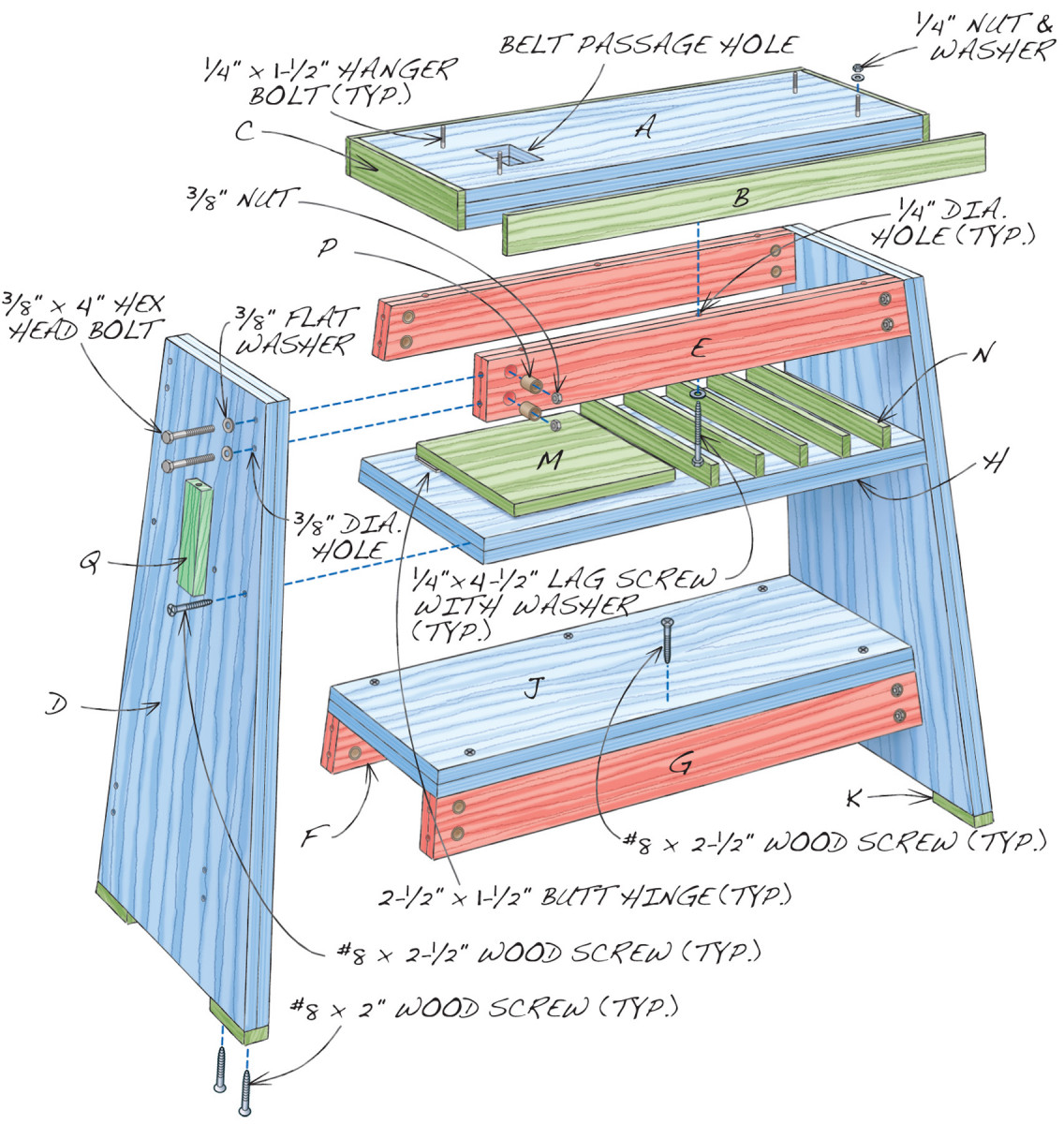
Fig. A Exploded View
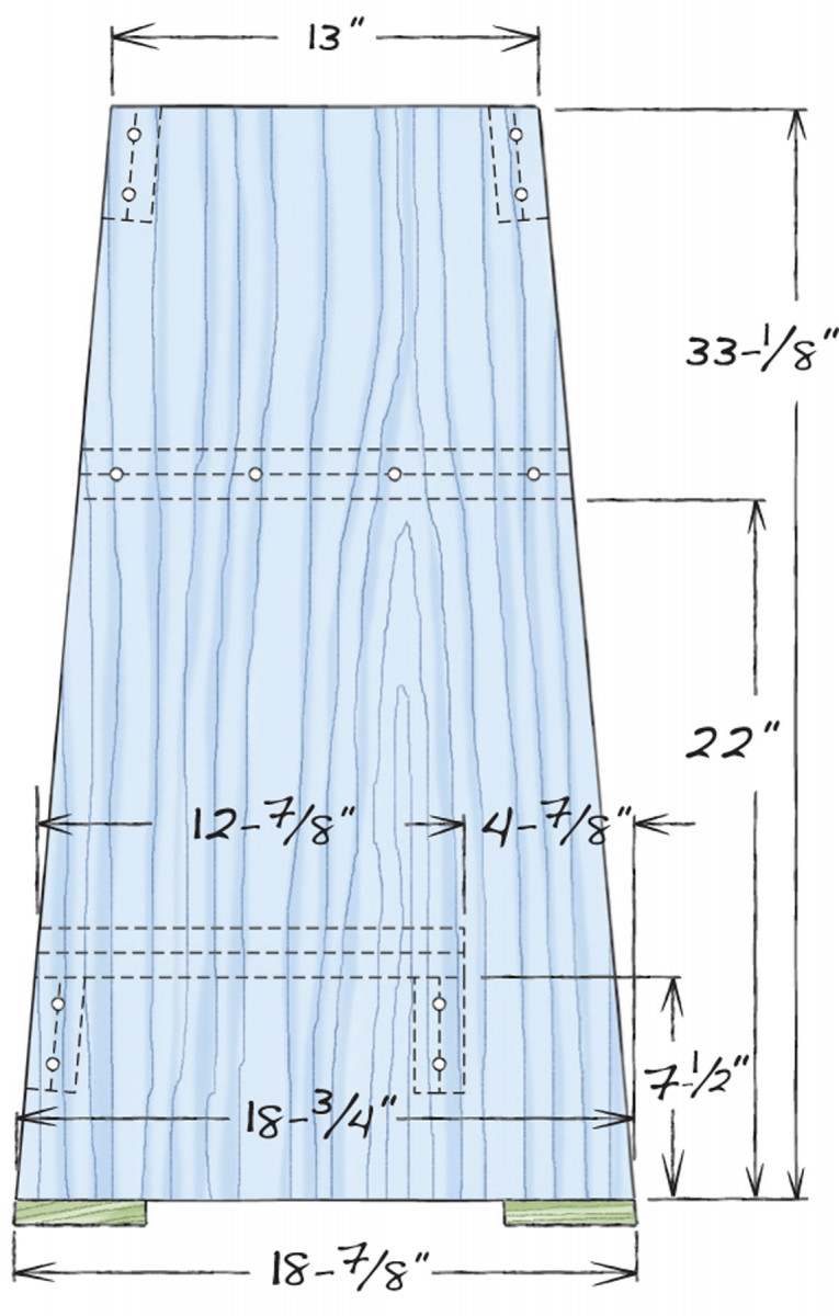
Fig. B Leg Detail, End View
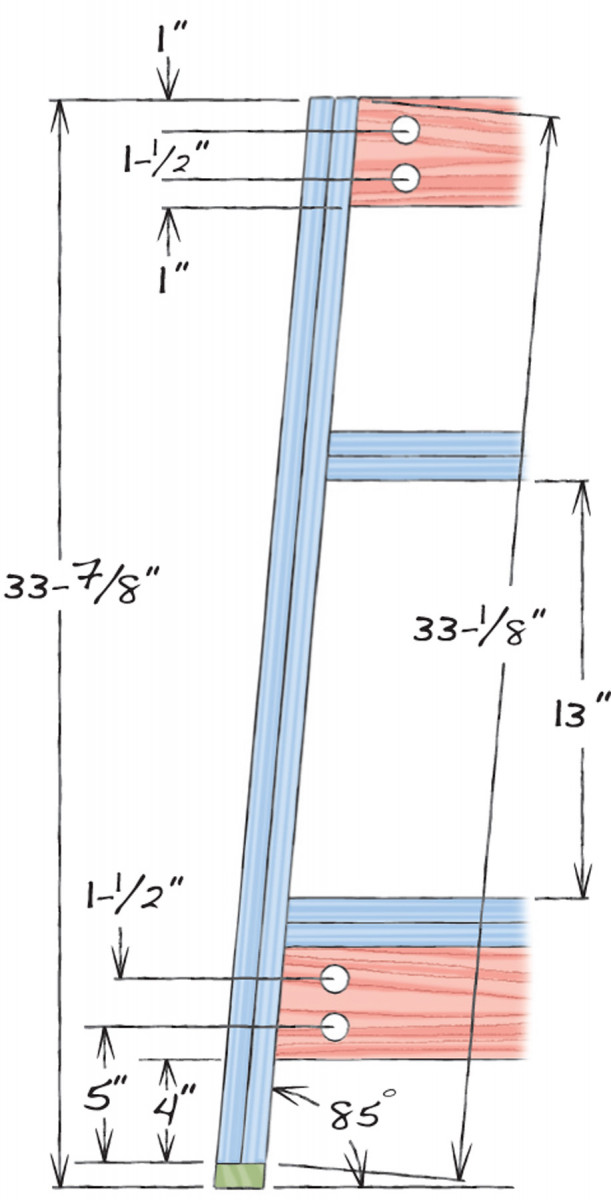
Fig. C Leg Detail, Front View
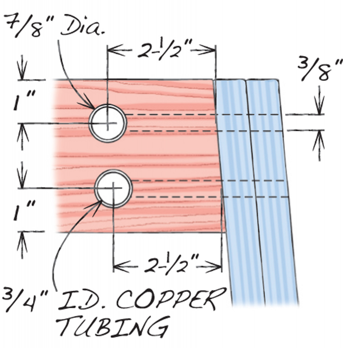
Fig. D Joint Detail
Cutting List
|
Part |
Name |
Qty. |
Material |
Th x W x L |
|
Top |
2-1/8″ x 14″ x 34″ |
|||
|
A |
Interior |
1 |
3/4″ Baltic birch plywood |
2-1/8″ x 13″ x 33″ (b) |
|
B |
Edgebanding front & back |
2 |
Oak |
1/2″ x 2-1/4″ x 34″ (c) |
|
C |
Edgebanding ends |
2 |
Oak |
1/2″ x 2-1/4″ x 13″ (c) |
|
Base |
33-7/8″ H x 38-7/8″ W x 18-7/8″ D (a) |
|||
|
D |
Legs |
2 |
3/4″ Baltic birch plywood |
1-3/8″ x 33-1/8″ x 18-3/4″ (d) |
|
E |
Top rails |
2 |
3/4″ Baltic birch plywood |
1-3/8″ x 3-1/2″ x 30-3/4″ (d) |
|
F |
Bottom back rail |
1 |
3/4″ Baltic birch plywood |
1-3/8″ x 3-1/2″ x 35-1/4″ (d) |
|
G |
Bottom front rail |
1 |
3/4″ Baltic birch plywood |
1-3/8″ x 3-1/2″ x 35-1/4″ (d) (e) |
|
H |
Top shelf |
1 |
3/4″ Baltic birch plywood |
1-3/8″ x 15″ x 32-1/8″ (d) |
|
J |
Bottom shelf |
1 |
3/4″ Baltic birch plywood |
1-3/8″ x 13″ x 34-5/8″ (d) |
|
K |
Feet |
4 |
Oak |
3/4″ x 1-1/2″ x 4″ |
|
M |
Motor mount |
1 |
3/4″ Baltic birch plywood |
3/4″ x 12″ x 12″ |
|
N |
Tool dividers |
5 |
Oak |
1/2″ x 1-1/4″ x 14-1/2″ |
|
P |
Copper tubes |
16 |
3/4″ i.d. x 1-1/2″ |
|
|
Q |
Knock-out bar holder |
1 |
Oak |
1″ x 2″ x 6″ |
a) Dimensions will vary depending on the lathe’s size and your height b) Three layers of 3/4″ Baltic birch plywood
c) Cut oversize, then trim
d) Two thicknesses of 3/4″ Baltic birch plywood
e) Do not angle top and bottom of front rail
Make the parts
First determine your stand’s height and length (see “Sizing Your Stand,”below). This stand is designed for a person about 5′ 8″ tall and a lathe that is 28″ long with an axis 9″ above its base. (I built this particular stand for a Vicmarc VL100.) Adjust the cutting list if necessary to fit your height and your lathe’s dimensions.
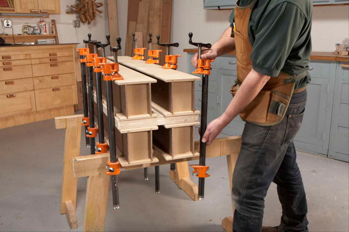
1. Glue two sheets of 3/4″ Baltic birch plywood face-to-face to make the legs. Use torsion beams or other large cauls to flatten the plywood and to provide even pressure.
Most of the plywood parts are made from two pieces glued together, face-to-face. Cut the pieces for these parts slightly oversize (Fig. A, Parts A, D, E, F, G, H and J). Glue them together (Photo 1).
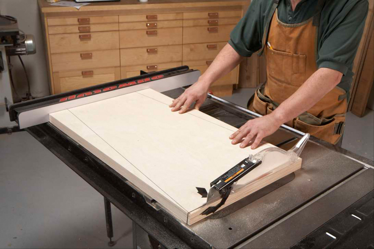
2. Cut a 5° angle on the top and bottom of each leg. This angle creates the side-to-side splay.
Cut the top interior (A) to final size. Glue edge banding on all four sides (B and C, Fig. A). Trim the edging flush with the interior.
Double-splayed legs are the key to the base’s stability (Figs. B and C). Use your tablesaw or circular saw to cut the top and bottom ends of the legs at 5° (Photo 2). Before you cut each leg, make sure these angles lean the same way, not in opposite directions. Lay out and cut the tapers on the long sides of the legs (Photo 3).
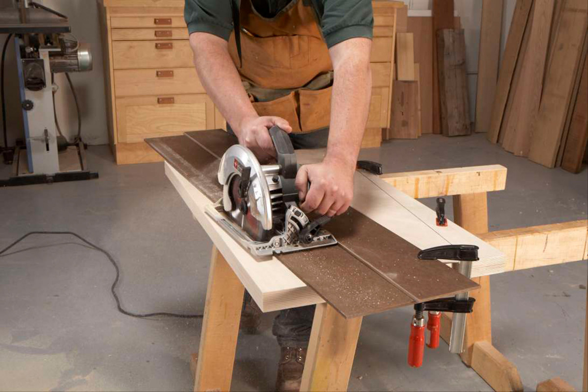
3. Use a saw guide and a circular saw to taper the legs.
Rip the rails (E, F and G) and shelves (H and J) to final width. Trim the pieces to length, cutting their ends at 5° in opposing directions. (Leave the top shelf extra-long for now, so you can adjust its position later, if necessary.) In addition, cut the shelves’ front and back edges, and the rails’ top edges, at 5°. On the bottom shelf, leave the front edge square. (Note that the front bottom rail is not angled to follow the legs’ taper. It is set back so you won’t bump your ankles.) Make the tool dividers (N) and fasten them to the top shelf.
The fastening system
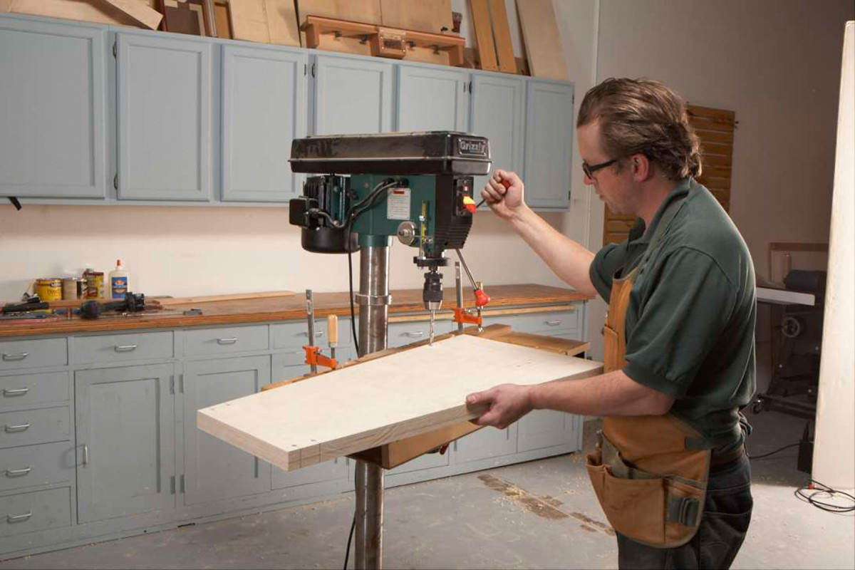
4. Drill holes angled at 5° for the bolts that will join the stand. Make the rails from doubled-up plywood, then cut their ends at 5°. Temporarily assemble the base with clamps.
To make the joints, start by laying out the bolt-holes in the legs (Fig. C and D). Tilt your drill press table to 5°, put a 3/8″ bit in the chuck and drill the holes (Photo 4). Use a fence to ensure that all the holes are the same distance from the tapered edges of the legs. Reset the fence for the front bottom rail holes.
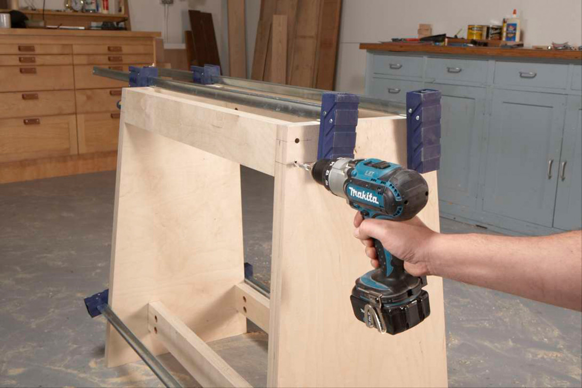
5. Drill into the rails through the holes in the legs. Disassemble the base.
Temporarily clamp together the legs and all four rails. Using a hand drill and the same 3/8″ bit, extend each bolt-hole into its corresponding rail (Photo 5). Disassemble the base. If necessary, drill these holes deeper.
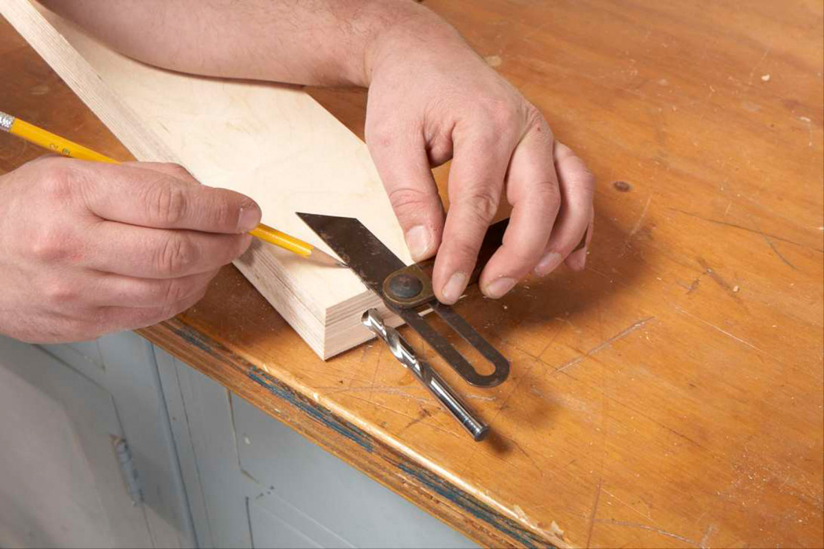
6. Insert the same drill bit into the rails. Using a sliding bevel, transfer the bit’s angle to the rail’s face. This enables you to find the exact center of the holes for the copper tubes that will hold the nuts.
Lay out the holes for the copper tubes that will hold the nuts directly from the holes you just drilled. First, draw a centerline across each hole. Insert the 3/8″ bit. Adjust a sliding bevel so it’s parallel to the bit (each hole may lean at a slightly different angle). Place the bevel adjacent to the hole’s centerline and draw a line down the face of the rail (Photo 6). Mark the center of the copper-tube hole on this line (Fig.D).
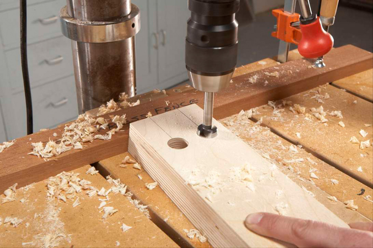
7. Drill holes for the copper tubes using a 7/8″ Forstner bit. Precision is important for a strong joint and easy assembly.
Reset the drill press table to 90° and drill the copper-tube holes all the way through the rails using a 7/8″ Forstner bit (Photo 7).
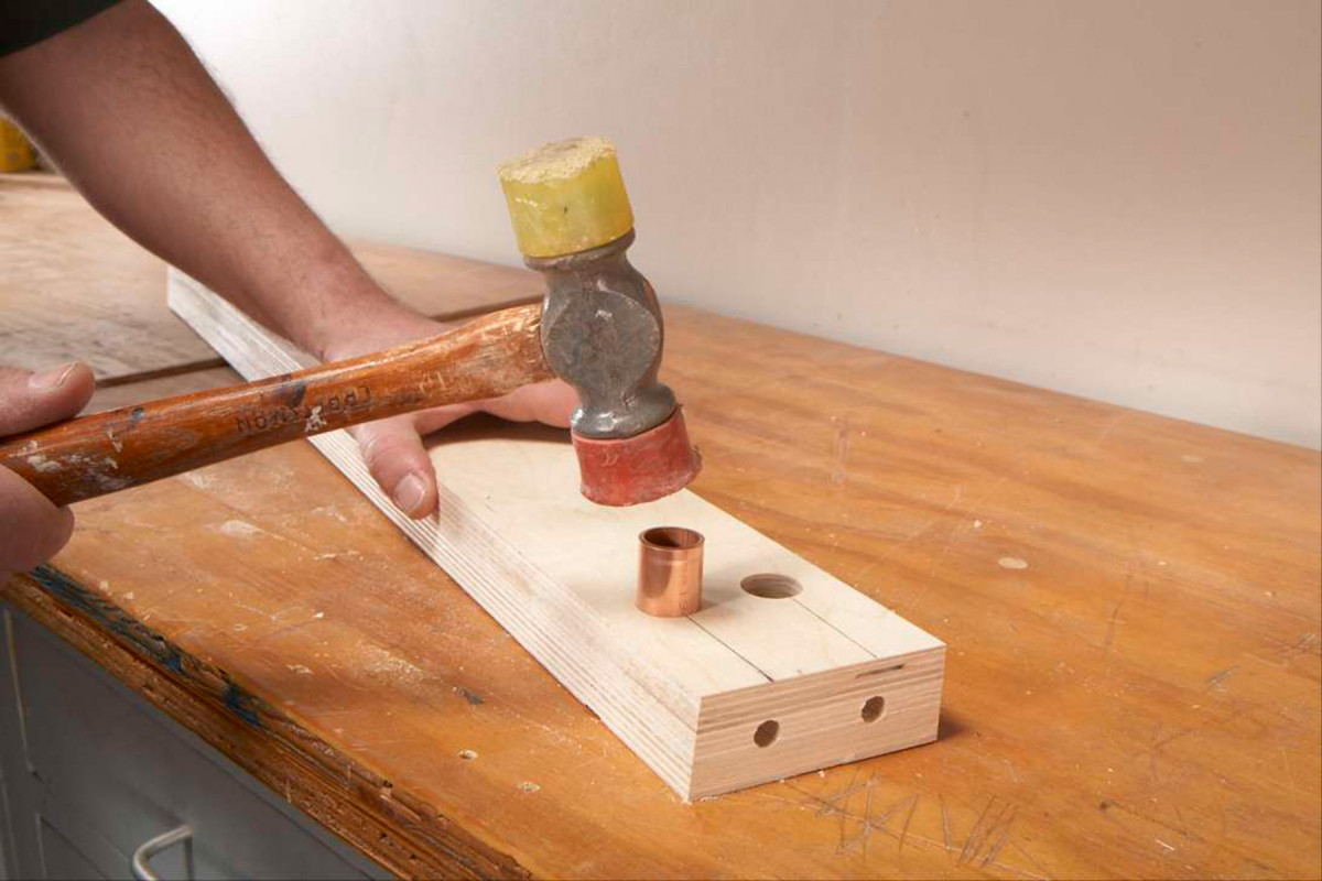
8. Tap copper tubes, made from copper pipe, into the holes. Drill through the ends of the rails and through the tubes to finish the joint.
Cut 1-1/2″ lengths of 3/4″ i.d. copper pipe (P) and tap them into each hole (Photo 8). Put the 3/8″ bit back in the drill. Push the bit into each bolt hole and drill through the near side of each copper tube.
Sizing Your Stand
“One size fits all” doesn’t work for a lathe stand—its height should suit your height.
You’ll need two measurements to calculate your stand’s height. First, if you’ll use a floor mat, stand on top of it. Bend your arm at the elbow to form a 90° angle. Measure the distance from the floor to the top of your fingers. Second, measure the distance from the center of the lathe’s spindle to the bottom of the lathe’s base. Subtract this distance from your hand-height—this is the ideal height for your stand.
The length of the stand depends on more than just the length of the lathe. You’ll need enough room at the stand’s left end so that your feet won’t bump into its leg. When you’re working out your stand’s dimensions, drop an imaginary plumb line from the chuck’s face to the floor. Allow about 10″ between the plumb line and the inside face of the leg.
Assemble the stand
Drill holes through the top rails for the lag screws that fasten the top. Clamp the legs and all of the rails together again. Insert a bolt through each hole. Slide a nut into the copper tube, hold it against the bolt with a flat-bladed screwdriver, and tighten the bolt.
Attach the shelves and feet (K) using countersunk wood screws. The exact position of the top shelf will depend on the length of the motor’s drive belt. After determining the top shelf’s proper height, cut it to length. To fasten the top shelf, mark its location, then tip the base upside down. The shelf will stay put because its ends are tapered. Run screws through the legs and into the shelf.
Attach the top. Position your lathe on the stand. (If your lathe has a separate motor, place it on the upper shelf about where it will go. Line up the lathe’s pulley with the motor’s pulley.) Mark the lathe’s mounting holes. Mark the passage hole for the belt (Fig. A). Bolt the motor to the motor mount (M) and attach the motor mount to the top shelf using hinges.
Remove the lathe and cut out the belt-passage hole. Pre-drill holes for the hanger bolts that will fasten the lathe to the stand. Install the hanger bolts and mount the lathe. Finally, screw on the knock-out bar holder (Q) and a hanger for your wrench. Apply finish if you wish.
Special thanks to Bill Hull of Norman, OK, who helped design my original stand more than 20 years ago—it’s still going strong!
Shopping List
• Sixteen 3/8″ x 4″ hex head bolts
• Six 1/4″ x 4-1/2″ lag screws
• Sixteen 3/8″ flat washers
• Sixteen 3/8″ hex nuts
• Four 1/4″ x 1-1/2″ hanger bolts
• Ten 1/4″ flat washers
• Four 1/4″ hex nuts
• One pair 2-1/2″ butt hinges
• One piece of 3/4″ i.d. x 24″ copper pipe
• Three 3/4″ x 5’ x 5’ sheets Baltic birch plywood
• Two bd. ft. hardwood
Here are some supplies and tools we find essential in our everyday work around the shop. We may receive a commission from sales referred by our links; however, we have carefully selected these products for their usefulness and quality.


Nice project, but I don’t see Figure A to cut the parts. Is that available?
Sorry Peggy, that’s been fixed!